Sunday, April 27, 2014

Finalized Electrical/Program/Mechanical Aspects, Labeled Important Items, Tested Final Robot - Matt/Mike/Patrick

Friday 4/25

Matt tested the GPS and compass making the final adjustments to offsets and other key values.  He then soldered a relay to the gun so it would release projectiles when a signal was given.  Matt and Patrick then tested the airsoft gun to make sure it would fire.  It didn't.  This is because EMF spikes were occurring, the gun had plastic shavings from the cuts, and the four 1.5V rechargeable batteries we were using couldn't provide enough power to the gun motor.  At first we swapped the airsoft gun with the nerf gun.  The same problems were still present.  To fix this we decided to use another battery.  The nerf gun was too heavy so we switched back to the airsoft gun after Patrick used compressed air to clean it.

Mike spliced wires for the master switch ad soldered them together to make the LED only turn on when the switch is on.  He also soldered wires to each guns.  With help from Matt, he then soldered wires to the relay.  He prepared the nerf gun to act as a backup just in case the airsoft gun didn't work.  He then helped Patrick label.

I, Patrick, made labels for the various electrical components including the on/off of the master switch, X/Y axises of the gimbal, GPS/gimbal boards, and the 5V/ground rail.  After Matt discovered the gun battery need to be switched, I took off the old ones, and mounted my 7.2V NiMH using zip ties.

After we felt everything was wired properly and where it needed to be, Matt and Patrick cleaned up the wiring.  We tested the final program outside.  Matt, Patrick, and a student off the street volunteered to have projectiles from the immobilization device launched at them.

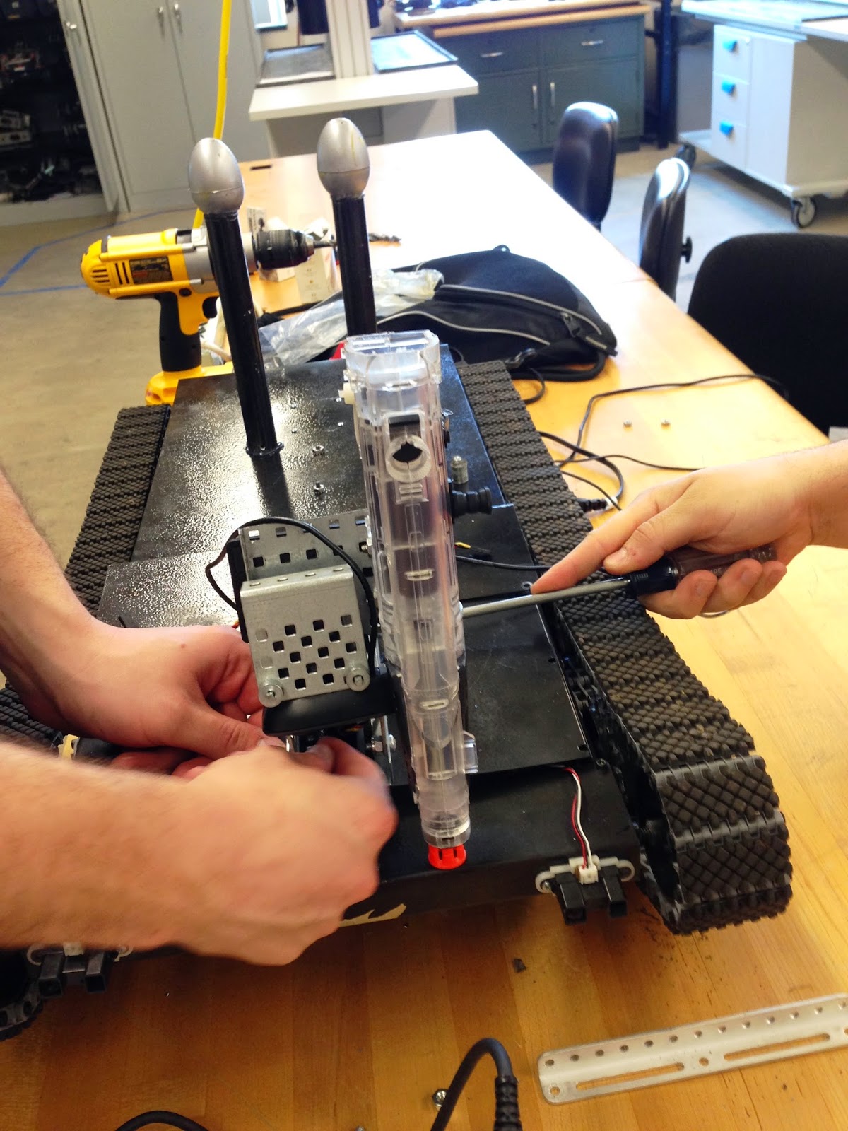
New Gimbal and RC Camera
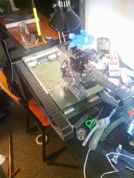
Shela Moving Towards Helsel
Labels for Electrical Parts
Initial Labels for Switch and Gmibal
Mike Testing Airsoft Gun
Brains Labeled
Nerf Gun Firing Test
New Battery for Gun, BBs Loaded
Shela's Test Victim: Patrick
Shela Firing Gun W/ Warning Light
Shela Patrolling Eberly
Shela Patrolling Eberly Part 2
Shela 2.0 Front View
Shela 2.0 Rear View
Shela 2.0 Side View
Shela 2.0 Isometric View (Left)
Shela 2.0 Isometric View (Right)


Rewired Switch, Shela Testing - Matt

Thursday 4/24

Matt tested all aspects of the robot and tweaked the program as necessary.  Testing included re-calibrating the compass and GPS sensors, motors, airsoft gun releasing projectiles, gimbal sweeping, etc.  He also rewired the master switch, after he realized it only would turn the onboard LED on and off.

Compass/New Gimbal Calibration, IR Integration, New Gimbal/Switch/Light Mounted, Wired Switch/Light, Rewrote Gimbal Sweep - Matt/Mike/Patrick

Tuesday 4/22

Before class, Mike took the old gimbal apart and rebuilt it so it would be stronger, smaller, and not as shaky.  The camera is now on the right underneath the gun and no longer sweeps.

Matt tested the new gimbal.  It is much stronger and smaller than before and it doesn't wobble, sway and give as much too.  He then tested the compass outside, but still had issues since the robot would spin in circles.  After class, Matt rewrote the compass program, integrated the IR, and finished soldering and wiring the switch and light.  He had to resolder the switch since Mike accidently made the leads too short.

Mike, with help from Patrick, mounted the new gimbal.  He then cut the positive lead (wire) for the battery so the switch could be soldered in.  He also soldered 5V super bright red LED to 330 Ohm resistor to be used in place of the 12V LEDs in the warning light.

Patrick punched a hole for the warning light on the cover, first drilling a hole for the the punch.  I then drilled a hole for the exposed wires so they would be as hidden as possible.  I also drilled a hole for the switch.

Mounting New Gimbal
Wiring Up New Gimbal
Mike Soldering Warning Light
Master Switch Mounted, Gimbal Wires Cleaned Up
Warning Light Mounted

Wednesday, April 23, 2014

Shela Testing (W/ Important Things Mounted): Compass, GPS, Gimbal, Gun - Matt

Monday 4/21

 Matt tried to test various aspects of the robot on the new chassis.  The compass would not work for some reason.  When he tested just the compass it would work, but if it was in the overall program it would not work.  The gun and gimbal were also not working.  If he fired the gun without the gimbal moving, it would work.  The gun was somehow feeding back to the servos controlling the gimbal, making the gun and camera look in one direction instead of sweeping.  After a short test (about 1 minute), the gimbal fell apart just like the old chassis did (we used VEX).  He tried to think of ways to fix the gimbal but nothing worked.

Tuesday, April 22, 2014

Airsoft Gun Modifications, Testing, Mount; Nerf Gun Modifications; Capacitor Bank; IR Mount; Gimbal Testing - Matt/MIke/Patrick

Friday 4/18

After the airsoft gun was mounted, Matt was able to test the shooting mechanism by "shooting blanks," or giving power to the gun with the trigger pushed, safety off and no BBs.  Sometimes the gun would get stuck; we aren't sure why.  He also tested the gimbal to see if it could still move with the gun on it; it was able to move.  An issue with the gimbal kept causing problems.  The gimbal, despite being geared down, still had a lot give and sway to it.  The gun was then all over the place.

As a backup to the airsoft gun, Mike continued to work on the nerf gun.  He cut it to make it as small as possible.  Mike then soldered a capacitor bank for the alkaline batteries.  While in the soldering state of mind, he also soldered leads to the metal springs on the airsoft gun (for the batteries normally) and to a transistor so the gun would not need batteries to fire.

Patrick cut the airsoft to be as small as possible taking off unnecessary plastic including the battery cover, the fake magazine, buttstock, and sight.  I also made sure the safety was always off and trigger was pushed to ensure the gun would always fire when given power.  I used zip ties and a rubber band.  I then drilled holes in the airsoft gun so it could be mounted to the side of the gimbal.  I mounted the gun to the gimbal so it could be tested.  I then was able to mount the IR sensors to the front plate/cover.

Modified Airsoft Gun
Mounted Sabertooth and Brains
Mounted Airsoft Gun
Gun & Gimbal Testing
Shela (W/Cover, Gun, & Gimbal)

Painted Shela; Mounted Cover, Brains, Sabertooth Gimbal, Front Plate - Matt

Thursday 4/17

Matt spray painted Shela black, taking off or covering necessary items like the cogs and treads.  He was then able to mount the the cover, gimbal, and front plate using bolts and nuts along with hot glue as needed.  He mounted the brains and Sabertooth to the bottom of the cover.  He also cleaned up wiring.

The airsoft gun also arrived.  It is the Crosman Pulse M74DP.

Crosman Pulse M74DP
Mounted Cover
Mounted Gimbal, Front Plate, & Battery Cover

Friday, April 18, 2014

Mounted Battery Holds, Made Brains Cover, Cut Compass/GPS Antenna Mounts, Drilled Cover Holes - Matt/Patrick

Tuesday 4/15

Matt was going to remount the back plate and gimbal using the JB Weld but after discussing what happened to the joints with Dr. B, he decided to drill and tap holes instead.  We also decided to make the cover and back plate one piece instead of two; we also made a front plate.  Dr. B found a piece of sheet metal for the cover.  Matt marked and measured the metal to be cut to the proper length.

Mike missed class.

I,Patrick, cut mounts for the GPS antenna and compass since the chassis was interfering with them.  I marked and measured the cover/back plate and front plate to be cut and bent by Dr. B.  I then made a battery cover since the terminals would touch the cover.  I had to make it the height of the gimbal platform since that was higher than the battery.  To get rid of sharp corners made chamfers on the battery cover.  I then drilled and tapped holes in the side rails to keep the cover in place and mount the front plate.

GPS Antenna/Compass Mounts
Cover/Back Plate
Front Plate, Battery Cover, Brains Cover

Thursday, April 17, 2014

Mounted Back Plate, Gimbal, Sabertooth; Wire Cleanup; Shela Testing - Matt

Saturday 4/12

Matt was able to mount the back plate (part of the hinged cover) and the gimbal using JB Weld.  He then mounted the Sabertooth to the back plate using hot glue.  Matt cleaned up the wiring so it was all nice.  He then labeled the wiring using tape.  When Matt tried to bring Shela in on Tuesday the JB Weld mounts did not hold even though he was able to pick Shela up on Saturday by the back plate and gimbal with ease.  On Tuesday, Dr. B said to use a label maker to make it look nicer.  matt was able to test the gimbal and compass.  We already knew the gimbal worked since we had tested it before.  After testing the compass on the chassis and away from it, Matt realized the compass and the GPS (antenna) needed to be mounted on plastic or something else that is non metal.  The compass worked beautifully when not near metal, and was very sporadic when on the chassis.  Matt also tested Shela for power consumption. He determined using 4 AA  batteries would work best for the 5V items, since the regulators get very hot with Patrick's 7.2V battery.

Side View of Shela
Protective Foam For Matt's Laptop
Mounted Back Plate & Gimbal (JB Weld) 
Mounted Sabertooth (Hot Glue)


Monday, April 14, 2014

Cog Realignment, Shela 2.0 Basic Testing, Gimbal Mount, Spacers Drilled, New Idler Mounts, Brains Cover, Etc. - Matt/Mike/Patrick

Friday 4/11

Matt was finally able to test Shela.  He made basic temporary mounts for the brains and batteries using zip ties.  After he and Patrick tested Shela a few times, a problem started to become apparent.  The spacers were tightening up against the cogs; this made the cogs unable to free spin.  To fix this, Patrick drilled bigger holes in the spacers.  This lessened the issue but the cogs still weren't spinning very well.  This is because the cogs weren't flush with each other.  Since earlier versions of Shela were able to mount curbs and steps, we tried to make Shela 2.0 do the same.  Although we never tried the steps inside Eberly, we had to due to rain.  Unfortunately the robot was not able to climb the stairs.  It was however able to descend stairs and mount false curbs (screw, nut, & bolt boxes).

Before we made the holes bigger, Mike drilled holes in 3/8" spacers (using two 3/8" instead of one 1/2" and one 3/8") to make the cogs flush with each other.  Mike then started to come up with ideas on how and where to mount the brains, Sabertooth, laptop and battery.  The battery will be towards the front, the brains and Sabertooth will be placed on top of the laptop, and the laptop will sit behind the battery.  Mike also made the back plate that will be the stationary part of the hinged brains cover.

Once we realized the spacers needed to have bigger holes in them, I, Patrick, drilled 17/64" holes in the 3/8" spacers.  To fix the spacer tightening issue even more, I decided to use one 3/8" spacer and a nut on each side of the side rails.  I then mounted the gimbal after modifying its platform to fit on the new chassis.  After we determined the platform wasn't very sturdy, I decided to use the remaining part of the shelf as the platform; Dr. B used the grinding wheel to get rid of burrs.

Mike Prepping the Brains Cover for Cutting
Matt Wiring Motors so He Can Test Shela
Shela Moving Around During Test
Patrick Making Spacer Holes Bigger
Matt and Patrick Testing Shela
Shela Mounting Fake Curbs
Matt Taking Gimbal Off Its Platform
Shela W/ Gimbal (On Its Temp Mount)


Thursday, April 10, 2014

Mount Idler Cogs, Mount Treads, Nerf Gun Mods - Matt/Mike/Patrick

Tuesday 4/8

Matt drilled out the holes for the idler cog axles on the side rails.  He then figured out how to space the cogs using 1/4" bolts and spacers.  An issue resulted from this though: the holes on the cogs were not big enough and neither were the spacers.  To account for this, Matt started to drill the holes bigger, making the cogs be able to free spin. Before he drilled the cogs and spacers, he did a test piece.  He also tapped the side rail holes.  He then had to leave for his lab.

Mike modified the nerf gun so it would not need the trigger to fire anymore.  He did this by rewiring it.  He reduced the weight by taking off unnecessary parts; he will make it even lighter by cutting away excess plastic.  Since Matt had to leave, Mike finished drilling the bigger spacer and cog holes.  When we tried to attach the cogs, another problem arose: the nuts couldn't be put on due to the sides of the shelf.  To fix this, Mike cut little "v" notches in the shelf to make room for the nuts using the sawzall.  After the shelf was taken off to be cut (by Mike and Patrick), we decided to fix the other issue with the shelf.  The issue was the holes in the shelf to attach it to the side rails were not big enough and messed up the screws. We drilled holes bigger than the threaded ones in the side rails.  The new screws went in very easily (10-32s).

I, Patrick, helped Matt and Mike as necessary by holding various parts as necessary so they wouldn't shift as they were drilling and cutting.  While Mike set up the v notch cuts, I attached the idler cogs to the side rails by threading the spacers on the cog bolts and tightening a nut on the other side of the side rails. After the basic chassis was assembled, Mike and I determined the required length of the treads and made two complete, equal-in-length tank treads.  After Mike left, I was able to attach the treads to the cogs


Matt Drilling Hole in Test Piece
Mike Testing the Nerf Gun
Matt Attaching the Left, Elevated Idler Cog
Matt Drilling Hole in Idler Cog
Mike Prying Open Piece of Nerf Gun
Matt Tapping Idler Cog Bolt Holes
Mike Drilling the Remaining Cogs/Spacers
Mike Taking Shelf Off for "V" Notches
All Cogs On (Motors & Idlers)
Treads Attached to Cogs