Tuesday 4/1
We all decided how to make the motor mounts with some help from Dr. B. We decided to make a notch in the side rails for each motor. This was accomplished by taking measurements of the side rails and marking the the location of the motor mounting plates.
Matt and Mike measured the motors, mounting plates, and the side rails. They decided to make the motors as close to the edge of the side rails as possible to ensure it could mount curbs. They also took apart the basic chassis to allow for machining and measurement taking.
I, Patrick, helped Dr. B machine the side rails to make the motor notches and screw hole locations. I helped pinpoint part/machine zero [(0,0) on the x,y grid)]. Dr. B did a test run on a piece of wood. A motor fit but it was very tight. So he increased the size of the circle the program made. Even after this slight increase, the notch in the side rails was too small (the wood was a little more giving). To fix this, Dr B. increased the circle size a few thousandths of an inch and reran the program until the motors fit.
Due to ground clearance issues, the motors had to be slightly below the bottom edge of the side rails. This caused a little piece of the notch to break off and create sharp edges.
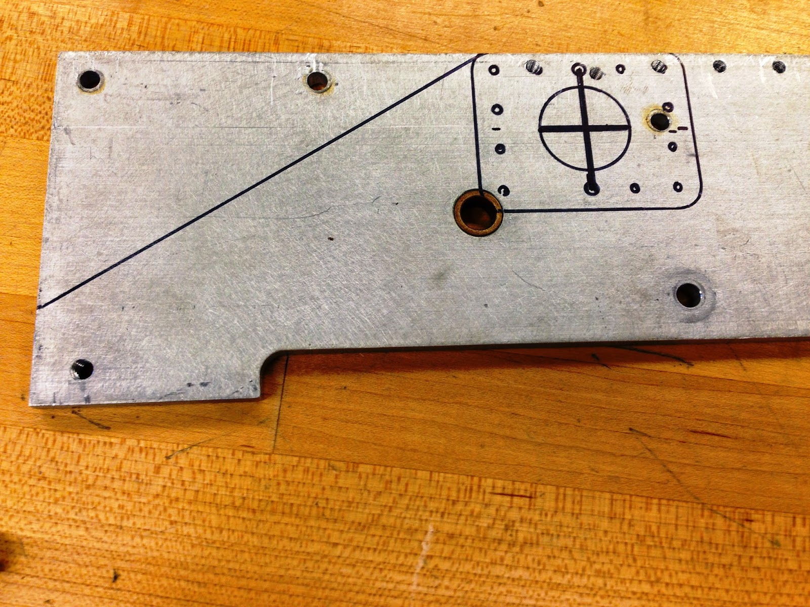+Part+1.JPG) |
| Front Motor Mount Placement |
+Part+2.JPG) |
| Rear Motor Mount Placement |
+Part+3.JPG) |
| Side Rail Machining (CNC) |
+Part+4.JPG) |
| Front Motor Notch |
+Part+5.JPG) |
| Rear Motor Notch |
No comments:
Post a Comment