Tuesday, April 22, 2014

Painted Shela; Mounted Cover, Brains, Sabertooth Gimbal, Front Plate - Matt

Thursday 4/17

Matt spray painted Shela black, taking off or covering necessary items like the cogs and treads.  He was then able to mount the the cover, gimbal, and front plate using bolts and nuts along with hot glue as needed.  He mounted the brains and Sabertooth to the bottom of the cover.  He also cleaned up wiring.

The airsoft gun also arrived.  It is the Crosman Pulse M74DP.

Crosman Pulse M74DP
Mounted Cover
Mounted Gimbal, Front Plate, & Battery Cover

Friday, April 18, 2014

Mounted Battery Holds, Made Brains Cover, Cut Compass/GPS Antenna Mounts, Drilled Cover Holes - Matt/Patrick

Tuesday 4/15

Matt was going to remount the back plate and gimbal using the JB Weld but after discussing what happened to the joints with Dr. B, he decided to drill and tap holes instead.  We also decided to make the cover and back plate one piece instead of two; we also made a front plate.  Dr. B found a piece of sheet metal for the cover.  Matt marked and measured the metal to be cut to the proper length.

Mike missed class.

I,Patrick, cut mounts for the GPS antenna and compass since the chassis was interfering with them.  I marked and measured the cover/back plate and front plate to be cut and bent by Dr. B.  I then made a battery cover since the terminals would touch the cover.  I had to make it the height of the gimbal platform since that was higher than the battery.  To get rid of sharp corners made chamfers on the battery cover.  I then drilled and tapped holes in the side rails to keep the cover in place and mount the front plate.

GPS Antenna/Compass Mounts
Cover/Back Plate
Front Plate, Battery Cover, Brains Cover

Thursday, April 17, 2014

Mounted Back Plate, Gimbal, Sabertooth; Wire Cleanup; Shela Testing - Matt

Saturday 4/12

Matt was able to mount the back plate (part of the hinged cover) and the gimbal using JB Weld.  He then mounted the Sabertooth to the back plate using hot glue.  Matt cleaned up the wiring so it was all nice.  He then labeled the wiring using tape.  When Matt tried to bring Shela in on Tuesday the JB Weld mounts did not hold even though he was able to pick Shela up on Saturday by the back plate and gimbal with ease.  On Tuesday, Dr. B said to use a label maker to make it look nicer.  matt was able to test the gimbal and compass.  We already knew the gimbal worked since we had tested it before.  After testing the compass on the chassis and away from it, Matt realized the compass and the GPS (antenna) needed to be mounted on plastic or something else that is non metal.  The compass worked beautifully when not near metal, and was very sporadic when on the chassis.  Matt also tested Shela for power consumption. He determined using 4 AA  batteries would work best for the 5V items, since the regulators get very hot with Patrick's 7.2V battery.

Side View of Shela
Protective Foam For Matt's Laptop
Mounted Back Plate & Gimbal (JB Weld) 
Mounted Sabertooth (Hot Glue)


Monday, April 14, 2014

Cog Realignment, Shela 2.0 Basic Testing, Gimbal Mount, Spacers Drilled, New Idler Mounts, Brains Cover, Etc. - Matt/Mike/Patrick

Friday 4/11

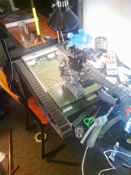
Matt was finally able to test Shela.  He made basic temporary mounts for the brains and batteries using zip ties.  After he and Patrick tested Shela a few times, a problem started to become apparent.  The spacers were tightening up against the cogs; this made the cogs unable to free spin.  To fix this, Patrick drilled bigger holes in the spacers.  This lessened the issue but the cogs still weren't spinning very well.  This is because the cogs weren't flush with each other.  Since earlier versions of Shela were able to mount curbs and steps, we tried to make Shela 2.0 do the same.  Although we never tried the steps inside Eberly, we had to due to rain.  Unfortunately the robot was not able to climb the stairs.  It was however able to descend stairs and mount false curbs (screw, nut, & bolt boxes).

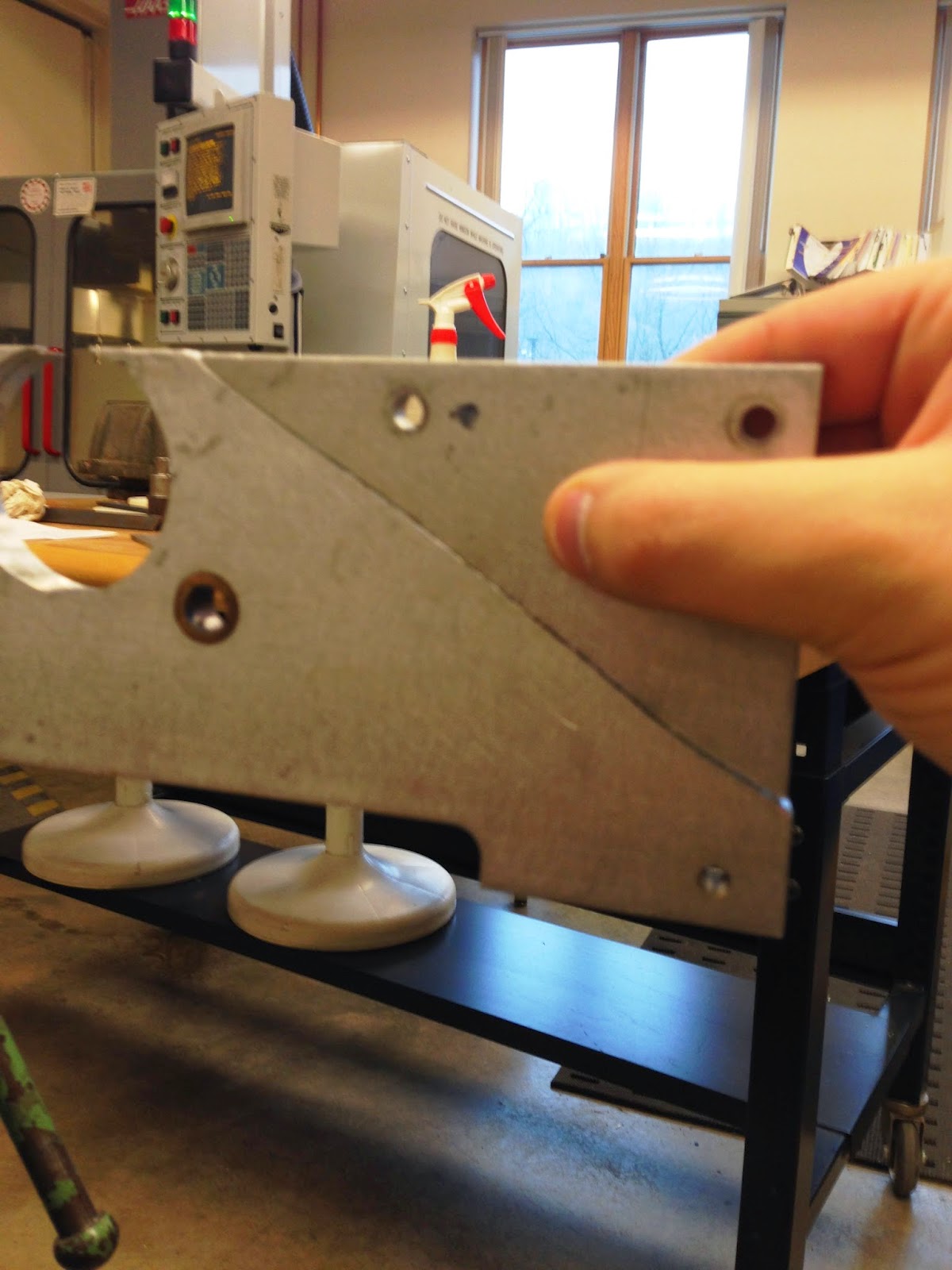
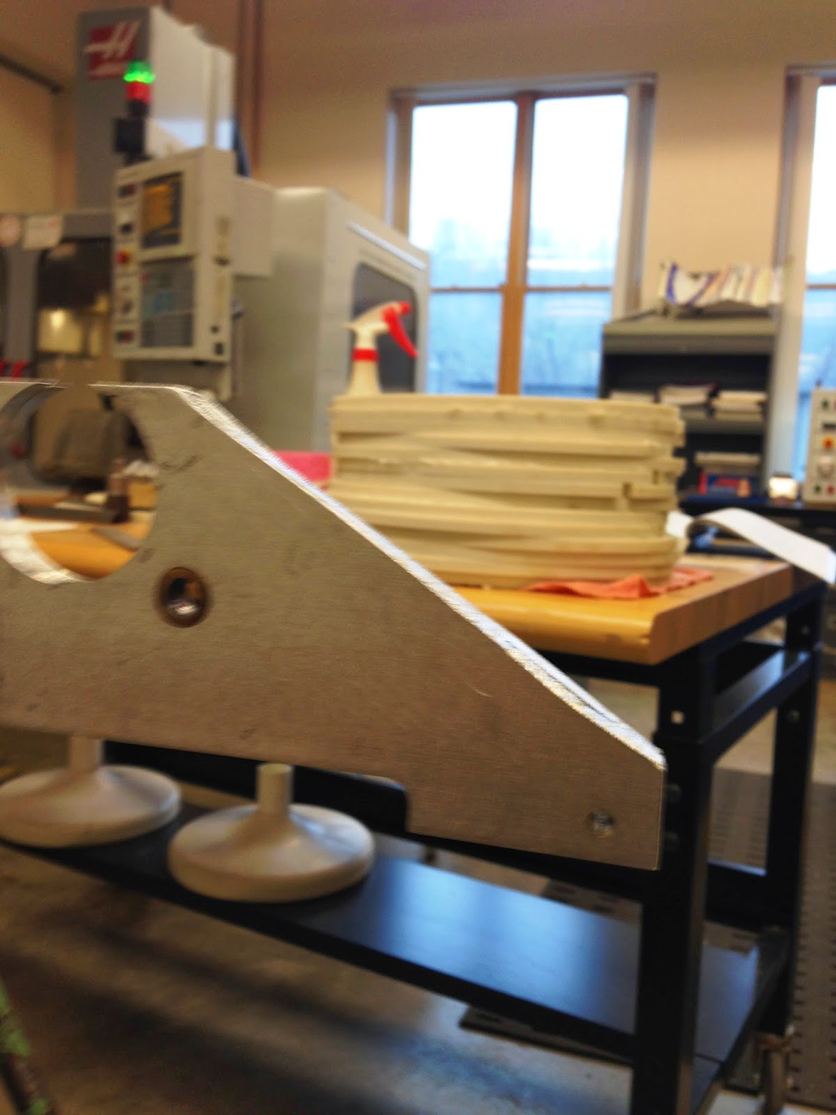
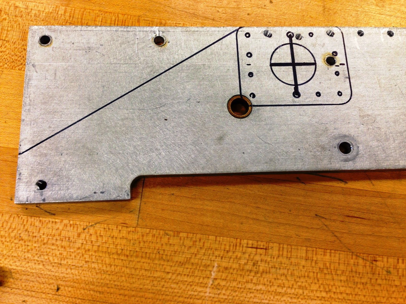
Before we made the holes bigger, Mike drilled holes in 3/8" spacers (using two 3/8" instead of one 1/2" and one 3/8") to make the cogs flush with each other.  Mike then started to come up with ideas on how and where to mount the brains, Sabertooth, laptop and battery.  The battery will be towards the front, the brains and Sabertooth will be placed on top of the laptop, and the laptop will sit behind the battery.  Mike also made the back plate that will be the stationary part of the hinged brains cover.

Once we realized the spacers needed to have bigger holes in them, I, Patrick, drilled 17/64" holes in the 3/8" spacers.  To fix the spacer tightening issue even more, I decided to use one 3/8" spacer and a nut on each side of the side rails.  I then mounted the gimbal after modifying its platform to fit on the new chassis.  After we determined the platform wasn't very sturdy, I decided to use the remaining part of the shelf as the platform; Dr. B used the grinding wheel to get rid of burrs.

Mike Prepping the Brains Cover for Cutting
Matt Wiring Motors so He Can Test Shela
Shela Moving Around During Test
Patrick Making Spacer Holes Bigger
Matt and Patrick Testing Shela
Shela Mounting Fake Curbs
Matt Taking Gimbal Off Its Platform
Shela W/ Gimbal (On Its Temp Mount)


Thursday, April 10, 2014

Mount Idler Cogs, Mount Treads, Nerf Gun Mods - Matt/Mike/Patrick

Tuesday 4/8

Matt drilled out the holes for the idler cog axles on the side rails.  He then figured out how to space the cogs using 1/4" bolts and spacers.  An issue resulted from this though: the holes on the cogs were not big enough and neither were the spacers.  To account for this, Matt started to drill the holes bigger, making the cogs be able to free spin. Before he drilled the cogs and spacers, he did a test piece.  He also tapped the side rail holes.  He then had to leave for his lab.

Mike modified the nerf gun so it would not need the trigger to fire anymore.  He did this by rewiring it.  He reduced the weight by taking off unnecessary parts; he will make it even lighter by cutting away excess plastic.  Since Matt had to leave, Mike finished drilling the bigger spacer and cog holes.  When we tried to attach the cogs, another problem arose: the nuts couldn't be put on due to the sides of the shelf.  To fix this, Mike cut little "v" notches in the shelf to make room for the nuts using the sawzall.  After the shelf was taken off to be cut (by Mike and Patrick), we decided to fix the other issue with the shelf.  The issue was the holes in the shelf to attach it to the side rails were not big enough and messed up the screws. We drilled holes bigger than the threaded ones in the side rails.  The new screws went in very easily (10-32s).

I, Patrick, helped Matt and Mike as necessary by holding various parts as necessary so they wouldn't shift as they were drilling and cutting.  While Mike set up the v notch cuts, I attached the idler cogs to the side rails by threading the spacers on the cog bolts and tightening a nut on the other side of the side rails. After the basic chassis was assembled, Mike and I determined the required length of the treads and made two complete, equal-in-length tank treads.  After Mike left, I was able to attach the treads to the cogs


Matt Drilling Hole in Test Piece
Mike Testing the Nerf Gun
Matt Attaching the Left, Elevated Idler Cog
Matt Drilling Hole in Idler Cog
Mike Prying Open Piece of Nerf Gun
Matt Tapping Idler Cog Bolt Holes
Mike Drilling the Remaining Cogs/Spacers
Mike Taking Shelf Off for "V" Notches
All Cogs On (Motors & Idlers)
Treads Attached to Cogs

Monday, April 7, 2014

Drilled/Tapped Motor Mount Holes, Disassembled Nerf Gun, Filed Burrs, Cut Side Rails, Cut Shelf, Chassis Reassembly - Matt/Mike/Patrick

Friday 4/4

Matt came in late due to a meeting.  After the screw holes were drilled, Matt tapped the holes to create threads for screws/bolts; this would also eliminate the need for nuts.  Since we chamfered the side rails, the shelf needed to be cut or bent so it wouldn't drag on the ground or curb.  We decided to just cut it to the size of the bottom side rail edge.  He then measured and marked the locations of the shelf cuts to allow for the motors.  With help from Patrick, he drilled holes to attach the shelf to the side rails.  We then put the chassis back together and mounted the motors.

Since Mike had experience with the drill press, he drilled the motor mount screw holes.  To help Shela 2.0 mount curbs better, we decided to make the front part of the chassis angled and to shorten the back end so the motor mounts were flush with the edge. We decided angle of roughly 20-30 degrees would work best.  After measuring and marking the cuts we wanted, he cut the side rails and shelf, using the sawzall and hacksaw.

To save time and get multiple things done at once, I did Mike's task of disassembling the nerf gun.  I got it most of the way but it just wouldn't budge without breaking.  I eventually got it apart though.  The shelf needed to have room for the motors but the sides of the shelf had to have a notch cut or something to allow for this.  With some help from Matt and Mike, I decided to just cut the sides away where the motors would be. Once all cuts were made, I filed the burrs.  To ensure the top idlers cogs would be free spinning (not have the axle move, just the cogs) we connected the two axles together.  This is not very good and we will have to make something better.

Mike Cutting Side Rails
Side Rail Chamfer "Before"
Side Rail Chamfer "After"
Patrick Filing Chamfers & Motor Nothces
Mike Drilling Motor Mount Holes
Matt Tapping Motor Mount Holes 1
Matt Tapping Motor Mount Holes 2
Mike Cutting Shelf For Motor Mounts 1
Mike Cutting Shelf For Motor Mounts 2
Possible Idler Cog Positions
Reassembled Chassis W/ Connected Top Cogs (much stronger)
Patrick Disassembling the Nerf Gun

Motor Mount Measurements, Side Rail Machining - Matt/Mike/Patrick

Tuesday 4/1

We all decided how to make the motor mounts with some help from Dr. B.  We decided to make a notch in the side rails for each motor.  This was accomplished by taking measurements of the side rails and marking the the location of the motor mounting plates.

Matt and Mike measured the motors, mounting plates, and the side rails.  They decided to make the motors as close to the edge of the side rails as possible to ensure it could mount curbs.  They also took apart the basic chassis to allow for machining and measurement taking.

I, Patrick, helped Dr. B machine the side rails to make the motor notches and screw hole locations.  I  helped pinpoint part/machine zero [(0,0) on the x,y grid)].  Dr. B did a test run on a piece of wood.  A motor fit but it was very tight.  So he increased the size of the circle the program made.  Even after this slight increase, the notch in the side rails was too small (the wood was a little more giving).  To fix this, Dr B. increased the circle size a few thousandths of an inch and reran the program until the motors fit.

Due to ground clearance issues, the motors had to be slightly below the bottom edge of the side rails. This caused a little piece of the notch to break off and create sharp edges.

Front Motor Mount Placement
Rear Motor Mount Placement
Side Rail Machining (CNC)
Front Motor Notch
Rear Motor Notch