Sunday, March 23, 2014

Compass Integration, Chassis Reinforcement - Matt/Patrick

Thursday 3/13

Matt modified the program so the robot now uses a compass to retrieve its heading.  The compass we are using is the LSM303D 3D compass and accelerometer carrier with a voltage regulator.  We used this compass because Arduino has a built in library for it, making it easy to to program and use.

I, Patrick, reinforced the front set of cogs (left and right) by using plates instead of a strip.  I also made platforms to connect the motors and mounts.  I did this to reinforce them and to reduce/eliminate how much they bowed.  I connected the front motors together; I did the same to the rear.

Previous Front Cog Reinforcement 
Current Front Cog Reinforcement
Motor Reinforcement Platform
Reinforced Motors and Mounts
GPS/Compass/ Motor Code Sample

Saturday, March 22, 2014

Simple Chassis (For Testing), GPS/RC Testing/Refining, Motors/Mounts Strengthening Ideas, Switch Connectors - Matt/Patrick

Tuesday 3/11

Matt started to make a simple eight wheel chassis so he could test the GPS, gimbal, and other components at his apartment.

Mike was not here that day.

Patrick researched potential reinforcements for the motors and mounts of the current chassis. I also connectors for the switch.

Patrick and Matt continued to test and refine the GPS and RC code so it would be accurate and responsive.

Switch Connectors (Short/Long)
Shela Mounting a Curb
Shela Mounting/Dismounting
Shela Climbing Steps

Monday, March 10, 2014

Blogger Issues - Patrick

3/10

For some reason Blogger adds a watermark of the play button to all videos.  Chrome can't upload background images due to an internal error.

Goolge Maps Integration Other GPS Options to Add - Matt


Sunday 3/9

Matt modified the LabVIEW GUI to show the current location of the robot and its destination in real time on Google maps.  This took about twenty minutes.  Matt also decided on more options to include.  These are using an Xbox 360 or Playstation 3 controller to control the robot when in RC mode and letting the user add multiple destinations and make them waypoints.

LabVIEW GUI - Google Maps (Robot/Destination)

Chassis Modification, GPS/Movement Testing, New Chassis Design, Nerf Gun DisassemblyMotor - Matt/Mike/Patrick

Friday 3/7

We all helped modify the chassis in one way or another.  Matt and Mike moved the front motors as close the front edge of the chassis as possible.  This was necessary because the first the time the robot tried to mount the curb, the front of the robot was getting caught on the robot.  We also had to have pictures taken for the school 's robotic website so we did simple things like have the robot move, wire the motors, and remount the motors.

Matt tested the GPS and robot with help from Patrick and Mike.  After modifying the chassis a bit, the robot climbed curbs with ease.  The locomotion testing involved Matt using RC (the keyboard) to control the robot.  An issue we were having was the batteries weren't lasting very long.  To account for this, we used various batteries and Patrick bought a brand new battery.  For the GPS testing, the robot "brains" (Arduino boards. Xbee, and GPS) were left off the robot so someone could easily walk around campus acting as the robot.  The GPS testing involved Matt sending the brains a destination and Patrick moving around to see what the robot's heading and location was in relation to the destination.

Mike disassembled the nerf gun to make the the nerf gun as small as possible since all we need from the gun are the dart holder and firing mechanism with motors. An issue we were having in earlier class periods was the treads were either too tight or too loose.  To account for this, Mike was going to add another set of cogs on each side so that they would tight but have some slack in them.  After testing the robot's movement outside, we realized the extra cogs weren't necessary and having more slack actually helped the robot mount curbs easier.

I, Patrick, moved the cogs at the top of the robot down one hole to give the robot treads some slack.  Eventually these were moved forward as previously mentioned.  I then helped Matt and Mike modify the chassis even more and test the robot.  I finalized the new chassis design with help from Dr. B.  It will use a metal shelf roughly 11" wide by roughly 2-3ft long.  It is a little narrower than our current chassis but we will have a stronger and more stable chassis as the tradeoff.  Since the bottom is a shelf, it will have a solid bottom that can be used to mount parts.  This new chassis will use siderails and metal rods similar to Project Palmer's chassis.

Motor Mount Modification
Temporary Sabertooth Mount For Testing
Shela vs. Mike (Size)
Brains Platform (Using 7.2V NiMH)
Disassembled Nerf Gun
Shela Locomotion Testing
More Testing
Shela 1.0
Shela 1.5

Unfortunately due to dead batteries, I did not get a video of the robot mounting the curb.

GUI, Weight Reduction - Matt/Patrick

Thursday 3/6

Matt decided to make a graphical user interface using labview. It has all the same options as the one that uses putty: RC, sentrybot, autobot.  He also added options for pretermined GPS locations including his apartment, Helsel, Eberly.

I, Patrick, reduced the weight of the robot by taking off anything that was unnecessary.  I left the parts I took off intact so that way they could be used again if I wanted to do so.  These pieces include the hinged roof over the control box, center part of chassis floor, motor mount reinforcements (didn't reinforce as much as I thought they would)

LabVIEW Front Panel - GPS GUI


GPS Program Mods, Antenna Mount, New Chassis Idea, Motor Testing- Matt/Mike/Patrick

Tuesday 3/4

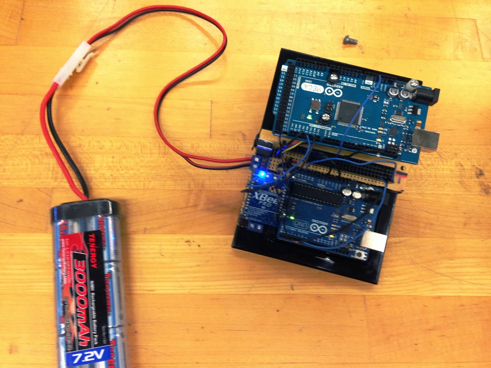
Matt refined the GPS program even more.  It is now accurate with in a few degrees.  Since he is done with the basic program, he and Dr. B decided to add a few more options.  Matt added an option for remote control (RC) and sentry only.  The user can now pick 3 options: autobot, RC, and sentry.  The autobot mode allows the user to enter a destination GPS coordinate.  The robot would then try to move to that location, looking for targets along the way and then react accordingly.  The RC mode allows the user to control the robot and "fire" the laser/nerf gun.  The sentry mode as the name implies makes the robot a guard... meaning it stays one spot and "shoots" any threats it detects.  This could be used in a building.

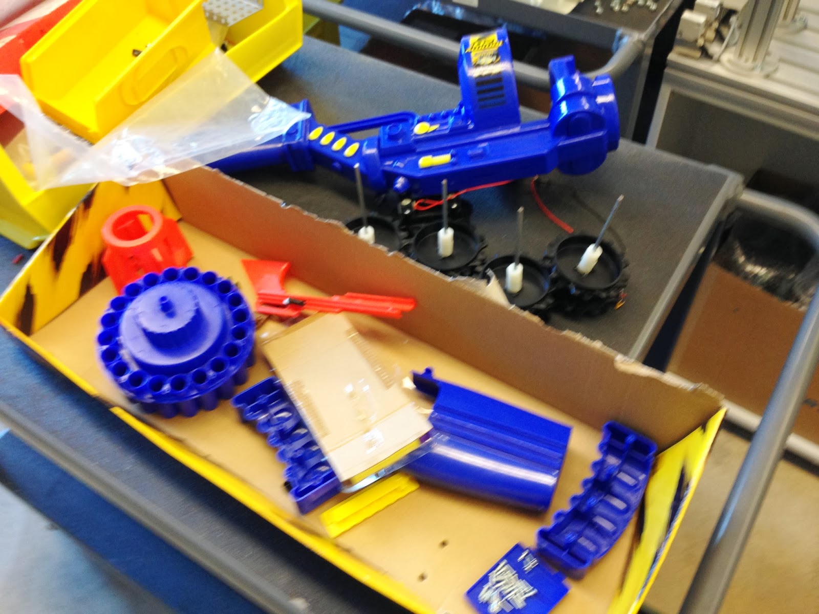
Mike mounted the GPS antenna so the range would be greater.  This antenna mount was not permanent just for testing.  A more stable and sturdier mount will be assembled on a new stronger chassis.  Mike also researched some new potential chassis builds to make "Shela," our robot stronger, (lighter?) and sturdier than our current chassis.  He found some inspiration on Google search for tank chassis. He then researched how to mount and modify the nerf gun.

I, Patrick, refined the basic motor program so the robot would turn only slightly in either direction.  I found the values for motor speed control were not what they should be...
       0 for full speed in one direction, 180 for full speed in opposite direction, and 90 for stop.  It turns out 30 was full speed in one direction, 160 for the other, and 90 for stop.
       Using this information, I made a small test program that had the robot turn roughly 10 degrees in each direction.  This is so the robot can avoid obstacles a bit easier when movie to a new location.  As class continued on, I realized that a new stronger chassis was a must.  I came up with a basic idea to use similar side rails to that of Project Palmer.  Dr.B then went over how to wire a master switch as a refresher.

Antenna Mount Test
Project Palmer's Basic Chassis - New Chassis Idea For Us